Jump to a question in this guide
- How does a private well supply a tap?
- Why are the well’s water level and the tap’s pressure different?
- What does a submerged well pump actually do?
- How does an above-ground jet pump differ?
- How can compressed air send water out of a tank?
- What happens through a normal start-and-stop cycle?
- What are the gauge, pressure switch and controller telling me?
- Why might a variable-speed system behave differently?
- Why does simultaneous water use matter?
- What can rapid cycling or a continuing run mean?
- Would a larger tank or a storage cistern solve the problem?
- What changes during a power interruption or freezing weather?
- Which measurements and records answer which question?
- What should qualified maintenance and handover include?
- What changes across Canadian regions and source editions?
- How would a fictional household investigate changed cycling?
- The pump adds energy to move water; the tank’s compressed air can deliver water between pump runs.
- Tank shell volume, usable water between control points and the well’s replenishment are different quantities.
- Rapid starts, a continuing run and weak delivery at one outlet need different assessment questions.
- Keep the well, pump, tank, controls, distribution and water-quality records connected without treating one result as all-system proof.
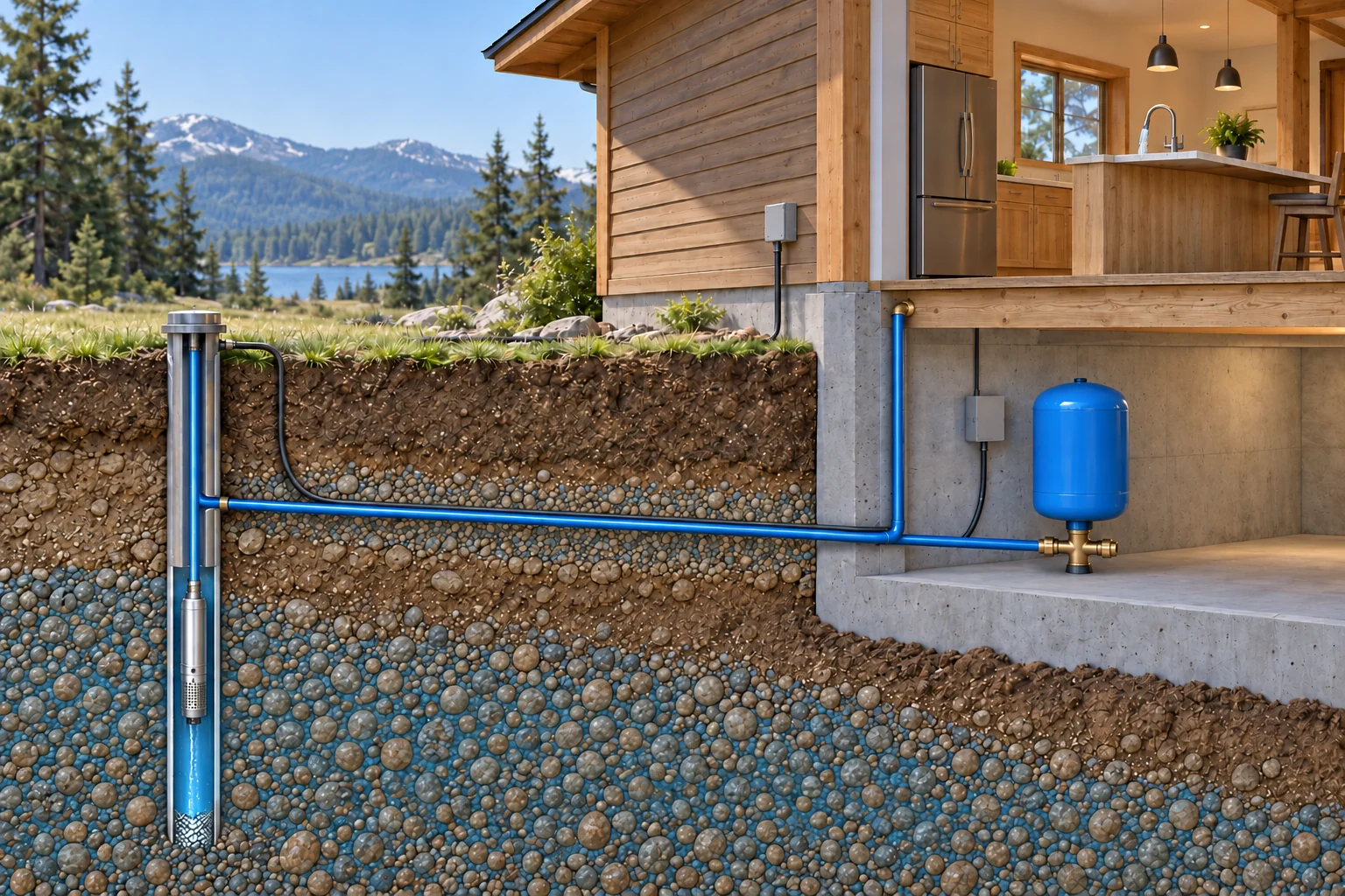
The submerged pump moves water upward in the well. The buried supply carries delivery toward the home, where a common route serves the pressure-tank branch and the branch rising toward the household. The tank can receive or deliver water as the operating cycle changes. The kitchen above shows the use that this system serves, while its concealed faucet connection is deliberately omitted.
About this illustration
Separate control lines and closed boxes are illustrative. The miniature pump shape is simplified and does not establish its motor, intake or stage arrangement; the dedicated corrected close-up teaches that relationship. The blue ground tint represents groundwater within granular material, not an open underground lake. Well depth, source yield, sanitary construction, buried depth, full household and treatment connections, electrical safety and water quality are not established. The right-hand supply stub is closed in this simplified context. This is a conceptual teaching model, not an assessment of your home.
9 picture lessons appear beside the questions in this guide. Use them to understand the explanation, then consider what it means for your home.
How does a private well supply a tap?
The well provides a place to collect groundwater. The pump supplies the energy needed to move that water toward the home. A pressure tank holds water alongside a compressed-air cushion, and controls decide when the pump should run. Pipes then distribute the water to fixtures and any treatment equipment. Following these jobs in order makes a familiar shower easier to understand without opening any equipment.
In a common arrangement, a pump submerged in the well pushes water up a pipe and along a buried connection. In another arrangement, a jet pump is located above ground and works with a different set of pipes and an injector. Both can feed a pressure system, but they should not be drawn as identical machines in different locations. Ask which arrangement the actual installation uses.
The tank is usually connected to the pressurized supply through a tee, a fitting that joins branches. It can receive water while the pump replenishes the system and deliver water toward the fixtures as demand draws on it. The explanation is not simply that every litre must pass through the entire tank before reaching a tap. Actual tank, treatment and branch connections should be identified together.
A water pipe and a control connection also do different jobs. The pipe carries water. A pressure switch or sensor responds to a condition, and the matched electrical equipment controls the motor. A closed box beside the tank is therefore part of the operating question, not another water-treatment vessel. Existing labels and records can help a professional identify it without exposing contacts.
Start the household record with the well location, available drilling information and the exact pump, tank and controller identities. Add treatment and any shared supplies as separate components. An unknown pump model remains unknown until a suitable record or qualified investigation establishes it; a tank brand does not identify the submerged pump.
This guide explains delivery and cycling. The established private-well guides cover water-quality evidence and a buyer’s broader well dossier. A pump that delivers a strong stream has not demonstrated that the water is appropriate to drink. If contamination or an advisory is suspected, obtain current local health advice while the equipment question is investigated.
The pump, tank and household supply form a connected delivery system
The submerged pump moves water upward in the well. The buried supply carries delivery toward the home, where a common route serves the pressure-tank branch and the branch rising toward the household. The tank can receive or deliver water as the operating cycle changes. The kitchen above shows the use that this system serves, while its concealed faucet connection is deliberately omitted.
Numbers identify the parts explained below.
- Well and submerged pump
The lower pump supplies the work to raise water through the connected pipe. The surrounding water-bearing ground and the pump’s delivery need different assessment records.
- Common supply and tank branch
The buried route enters the basement and joins the pressure-tank branch. A tank does not create groundwater or independently establish source replenishment.
- Household branch
The blue branch rises into the floor to represent distribution toward household use. The hidden connection to the kitchen faucet is not drawn, and the sink drain is not part of this supply lesson.
What does this illustration leave out?
Separate control lines and closed boxes are illustrative. The miniature pump shape is simplified and does not establish its motor, intake or stage arrangement; the dedicated corrected close-up teaches that relationship. The blue ground tint represents groundwater within granular material, not an open underground lake. Well depth, source yield, sanitary construction, buried depth, full household and treatment connections, electrical safety and water quality are not established. The right-hand supply stub is closed in this simplified context. This illustration explains an idea. It is not an installation guide.
Can the qualified provider identify this home’s actual well, pump, tank, controls and distribution route, keeping water quality as a separate question?
Explore this with HomeAI ↗Opens an editable question. Nothing is sent until you choose to send it.Follow a complete well-pump pressure cycle
Choose a step or play one 64-second reading pass. The pace and changing shapes explain a conceptual sequence; they are not real equipment timing, pressure, flow, settings or a test result.
- Water source: Groundwater → well pump → rising and buried supply.
- Pressure reserve: One tank branch connects to the common supply; the diaphragm separates air and water.
- Household demand: The common supply continues to the tap; no sanitary drain is shown.
- Control: A separate closed control responds to the matched condition and controls the motor.
Paused at step 1 of 8.
A household opens a tap
The open tap creates a demand for water. This conceptual example follows an on/off-controlled submersible pump and a diaphragm pressure tank. It is not a variable-speed arrangement or an instruction to operate equipment.
Useful question: Which pump, tank and control arrangement actually serve the home?
The complete lesson stays here as you read
A household opens a tap
The open tap creates a demand for water. This conceptual example follows an on/off-controlled submersible pump and a diaphragm pressure tank. It is not a variable-speed arrangement or an instruction to operate equipment.
Useful question: Which pump, tank and control arrangement actually serve the home?
The tank supplies water between pump runs
Compressed air pushes against the flexible diaphragm. Water leaves the tank through its one lower branch and joins the common supply toward the tap. The pump can be off during this part of the cycle.
Useful question: How much usable water does the matched tank provide between its actual control points?
The air cushion expands as water leaves
The lower water volume decreases and the upper air volume expands. Pressure falls in this illustrated cycle. Tank shell capacity and usable water between control points are therefore different quantities. The picture has no measured pressure or volume scale.
Useful question: Does the report distinguish tank volume, usable water and delivered pressure?
The matched control starts the pump
The pressure-responsive control reaches its operating condition and starts the matched motor circuit. The closed control box senses and controls; it does not carry the household water. No electrical contacts, setpoint or adjustment procedure are shown.
Useful question: Which identified control and current instructions explain the observed start?
The pump adds energy to the water route
The powered submerged pump moves water up the well pipe and toward the common household supply. This successful fictional cycle assumes an adequate source, available power and a suitable route. A running motor alone does not demonstrate useful delivery.
Useful question: What was measured about source availability and actual pump delivery?
Water replenishes the tank while demand changes
When delivery permits, water enters the tank through the same lower branch. The diaphragm moves and compresses the air cushion. Water can also serve the open tap from the common supply; every litre does not have to pass through the entire vessel.
Useful question: How do simultaneous uses and the actual pipe connections affect the system?
The control stops the pump at its operating condition
As the system reaches the matched stop condition, the control stops the motor. The drawing supplies no universal pressure setting, cycle duration or acceptable number of starts. Real control strategies and manufacturer requirements differ.
Useful question: Are start and stop findings tied to the exact equipment and conditions?
The stored pressure is available for the next demand
The air cushion and water remain in the tank for the next ordinary use. A change in cycling calls for an investigation of source, demand, delivery, tank and controls. This illustrated normal cycle has not tested water quality, protection or installed condition.
Useful question: Which changed observation and qualified follow-up answer the original question?
Why are the well’s water level and the tap’s pressure different?
Groundwater enters a well from the surrounding water-bearing material. Pumping removes water from the well while the surrounding formation replenishes it. The level during pumping can differ from the level after a suitable recovery period. These are source conditions, not pressure-gauge readings in the basement, and they require their own measuring methods and interpretation.
Pressure describes force per unit area at an identified point in the delivery system. Flow describes the volume moving over time. A pump has to raise water from its pumping level, move it through the route and provide the delivery required at the intended outlets. The level in the well and the pressure at a fixture are connected through that work, but they are not interchangeable measurements.
A well can contain water while a pump or pressure-system problem prevents useful delivery. Conversely, functioning equipment cannot make the surrounding formation replenish indefinitely at any requested rate. Ontario’s shortage guidance asks owners to consider source, equipment, demand and local conditions before selecting a remedy. A smaller stream alone does not select one of those causes.
A drilling record may give the depth, construction and observations from the original work. Later pumping records may concern another date, rate or configuration. Keep those differences visible. A number copied from the original record cannot automatically stand for the current water level, the installed pump setting or a guaranteed future household supply.
The professional question is how source availability and equipment delivery fit the actual demand. Give the provider ordinary-use history, previous work and any existing pumping assessment. Let them determine what source-level, recovery and delivery information is needed and how to obtain it safely. Do not run the well hard to create an informal capacity test.
Do not remove the well cap, lower a home-made probe or enter a pit to obtain a missing number. Those actions can involve contamination, electrical and confined-space hazards. A gap in the record should become a qualified measuring task, not an invitation to improvise access. The same boundary applies when a historic public leaflet describes procedures that require site-specific competence.
What does a submerged well pump actually do?
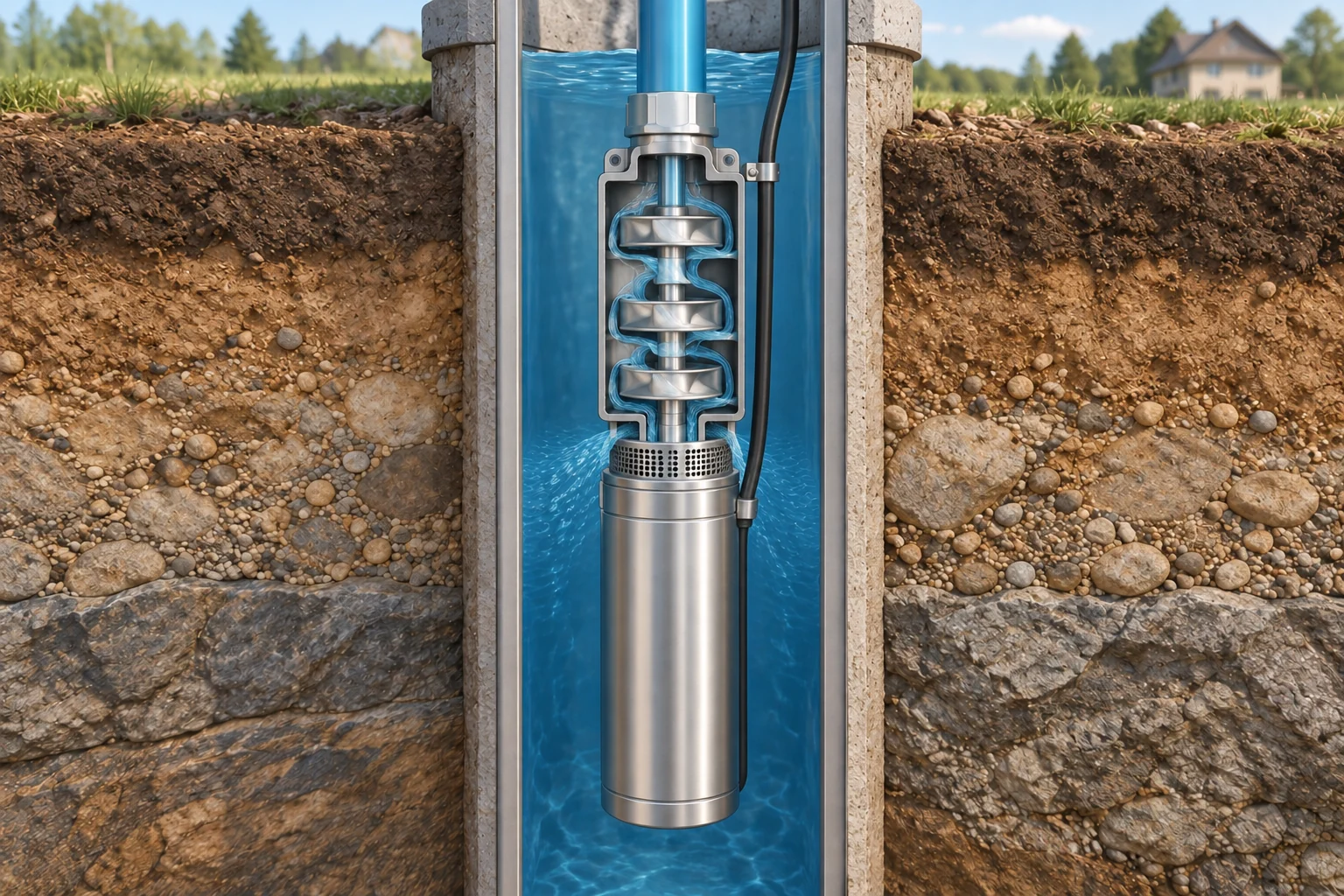
A submersible pump operates below the water surface in the well. Its motor turns water-moving parts inside the pump body. In the centrifugal arrangement illustrated here, rotating impellers move water through successive passages; diffusers guide it toward the next stage. The resulting delivery leaves through the outlet and rises in the connected pipe.
The motor and the water-moving stages are different parts of one machine. Electrical power makes the motor turn; the pump stages transfer energy to the water. The rising pipe then carries water away. An electrical finding, a pump-performance finding and a pipe-condition finding concern different links, even when the same service appointment investigates them.
Pump output depends on the work required of it. Raising water farther or delivering it against a different pressure changes the operating question. Alberta’s historical submersible-pump explanation illustrates why two machines with the same nominal motor power need not deliver the same combination of pressure and flow. Horsepower alone is therefore an incomplete replacement specification.
The pump also depends on appropriate source and operating conditions. Sand or other abrasives, insufficient water and dissolved-gas conditions can matter to particular installations. They are possible assessment topics, not defects established by a sound recording or a cloudy glass. Tell the well professional what changed and preserve any actual water or equipment findings separately.
A submerged pump can be difficult to identify from an ordinary house visit. The best available starting record may be the installation invoice, model information, pump setting and later service history. Pulling equipment from the well is specialist work. A homeowner should not attempt to retrieve it, bypass controls or substitute a repeated reset for diagnosis.
If replacement is proposed, ask how the selected equipment matches the well, pumping conditions, pipe route, electrical supply, controls and intended uses. Have the provider identify what will be retained and what will be checked afterward. A new pump is a changed component; its invoice does not establish the condition of every retained pipe, tank or treatment device.
The motor turns the pump; the stages move water upward
The lower motor turns the pump shaft. Water enters the screened intake above the motor and moves through the illustrated impeller and diffuser stages toward the top outlet. The connected pipe carries that delivery upward. Those jobs explain why a motor that can be heard or electrically assessed is a different question from useful water delivery through the whole route.
Numbers identify the parts explained below.
- Motor below
The sealed lower body represents the motor that turns the shaft. Its identity and electrical assessment belong with the pump record; no contacts or wiring task are exposed.
- Intake and pump stages
The screened region is above the motor, beneath the illustrated water-moving stages. An appropriate source and matched operating conditions matter to delivery; no failed component is diagnosed.
- Outlet toward the house
Water leaves through the upper connection into the rising pipe. Ask how the actual pump and route match source conditions and household demand rather than comparing motor power alone.
What does this illustration leave out?
The stage shapes, count, blue water and proportions are illustrative. They identify no actual model, lift, flow, pressure, source yield, electrical condition or installation detail. The picture is not a pump-pulling or service procedure. This illustration explains an idea. It is not an installation guide.
What identifies the installed pump, and which qualified findings distinguish source, pump and delivery-route concerns?
Explore this with HomeAI ↗Opens an editable question. Nothing is sent until you choose to send it.How does an above-ground jet pump differ?
A jet-pump system uses a pump above ground together with a nozzle-and-venturi arrangement. A venturi is a shaped passage that helps create the pressure conditions needed to draw in additional water. In the deep-well example described by Alberta, some pumped water travels down a drive line to the injector and returns with water drawn from the well.
That recirculating route explains why a deep-well jet arrangement can have more than one water connection toward the well. One path supplies the injector and another returns toward the pump. The pipe count is not a reliable owner identification method by itself: concealed work, another configuration or later changes may make a quick visual guess wrong.
The above-ground impeller still has a useful physical job. Its rotating vanes move water through the pump, with a portion going toward the pressure system. The injector and connected pipes contribute to the complete pumping arrangement. A replacement decision therefore needs more than matching the appearance of the visible motor or ordering the largest available pump.
Jet systems depend on the appropriate water-filled condition, often called being primed. Air entry, an obstructed injector or loss of the necessary supply condition can change delivery. These are alternatives a qualified provider can investigate. The fact that a machine runs without useful water does not establish which part failed and should not prompt repeated operation to see whether it recovers.
Do not remove plugs, pour water into the pump, adjust a regulating valve or pull a jet assembly using this guide. The Alberta leaflet includes historic priming and start-up procedures, but those instructions are not adopted here as a household task. Current equipment instructions, electrical safety and the actual well configuration must govern professional work.
When requesting service, describe the change in plain language: whether the motor was heard, which fixtures were affected, whether normal delivery returned and what work occurred beforehand. Ask the provider to identify the pump and injector arrangement, investigate the relevant paths and record the findings. Keep a reported loss of prime separate from a demonstrated cause of that loss.
How can compressed air send water out of a tank?
Air can be compressed much more readily than water. When a pump puts water into an appropriate pressure tank, the air cushion occupies less space and its pressure rises. When an outlet draws water from the system, the air expands and helps push stored water back toward the supply connection. This is why the pump need not start for every small use in a conventional cycling arrangement.
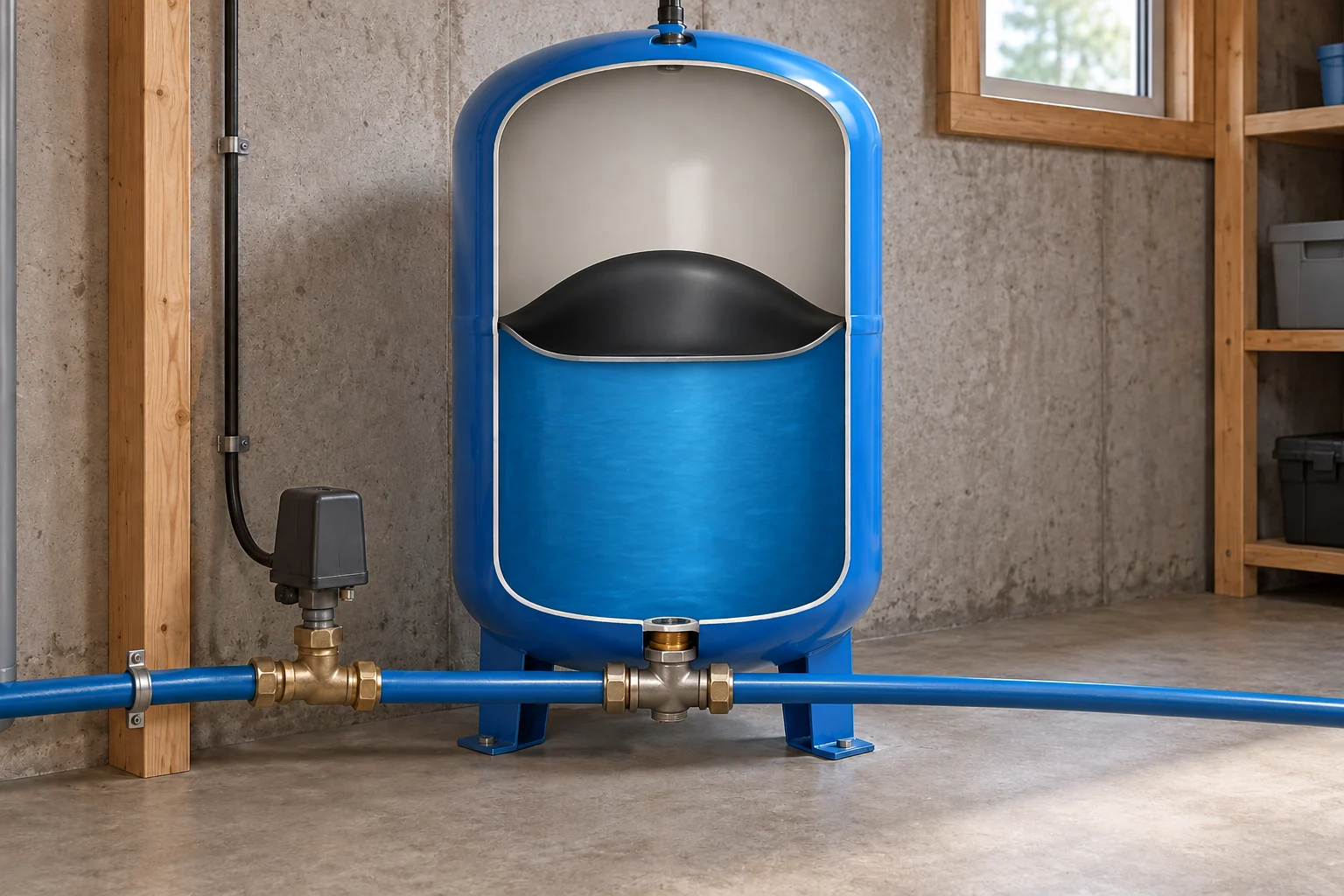
Some tanks keep air and water in direct contact. Others use a flexible diaphragm or air cell to separate them. The cutaway shows one separated-air concept; it is not the hidden internal arrangement of every tank with a similar shell. Tank identity matters because air-volume control, service and replacement questions differ between designs.
In an air-over-water tank, air can dissolve into the water over time. The intended air-control arrangement helps maintain the required balance. Alberta’s historical pressure-tank leaflet explains that too little air cushion can reduce useful delivery between pump starts and lead to more frequent cycling. It does not make every rapidly cycling system a confirmed waterlogged tank.
A separated-air tank has its own air condition, separator integrity and model-specific operating requirements. An outside photograph cannot establish them. A tap on the shell, the apparent weight or the position of a gauge needle is not a substitute for the appropriate qualified assessment. Do not use a household tyre gauge, compressor or drain procedure to check a tank from this article.
The water available between the system’s normal control points is often called draw-off or drawdown in tank literature. It differs from the shell’s total volume, because part of the vessel is occupied by air and the operating range matters. It also differs from well drawdown, which describes a change in water level at the source. Ask which meaning a quoted figure uses.
An installed tank therefore needs a matched description: its model, internal type, purpose, operating arrangement and usable reserve under the specified conditions. A larger shell may change the design question but does not by itself identify an appropriate solution. A professional should connect the tank selection and any findings to the pump and control arrangement rather than treat the vessel as an isolated purchase.
Compressed air helps deliver stored water between pump runs
The tank holds water alongside an air cushion, separated here by a flexible diaphragm concept. Water entering the lower connection compresses that cushion. When demand draws water out, expanding air helps send stored water back through the connection toward the supply. The bottom tee allows the tank to receive and deliver water without requiring every household litre to pass through the full tank first.
Numbers identify the parts explained below.
- Air cushion above
The upper space illustrates compressible air. The usable reserve depends on the identified tank and operating arrangement, not the shell volume alone.
- Separator and water
The curved separator keeps the illustrated air and water apart. A shell photograph cannot establish the real separator’s integrity or correct air condition.
- Bottom connection and tee
The lower water connection joins the common supply through a tee. Its job is different from the adjacent closed pressure-control enclosure.
What does this illustration leave out?
This is one generic separated-air concept. The diaphragm shape and volumes are illustrative; no air setting, usable reserve, actual internal condition, pressure rating or safe installation is established. Other tanks use different air/water arrangements. This illustration explains an idea. It is not an installation guide.
Which tank type and operating arrangement are actually installed, and what assessment supports a finding about changed reserve or cycling?
Explore this with HomeAI ↗Opens an editable question. Nothing is sent until you choose to send it.Three different meanings of stored water
- Tank shell volumeThe overall vessel size; not all of it is useful water reserve.
- Tank draw-offWater available between specified operating conditions.
- Well supply and recoverySource behaviour under stated pumping and recovery conditions.
No tank selection, source yield or operating pressure is calculated.
Further reading: Government of Alberta · Pressure Tanks, Agdex716(C31); Government of Ontario · Managing your water well in times of water shortage.
What happens through a normal start-and-stop cycle?
Begin with an ordinary demand, such as a tap opening. Water moves toward the outlet. In the illustrated conventional system, the tank’s air cushion can initially help supply that demand, so the pump may remain off while some stored water is delivered. This is useful stored delivery, not water being created or the well being permanently replenished.
As water leaves the tank, its air volume expands and the pressure condition changes. At the matched starting condition, the pressure control calls for the pump to run. Starting pressure is often called cut-in in equipment literature. The actual setting belongs to the identified system; this guide gives no pressure number, adjustment target or control-setting procedure.
The running pump then supplies the connected route. Household demand may continue at the same time. When pump delivery exceeds that demand under the actual conditions, some water replenishes the tank and compresses its air cushion. Understanding those simultaneous jobs is more useful than imagining the pump always fills the tank completely before a fixture can receive water.
When the matched stopping condition is reached, the control ends the pump run. Equipment literature may call this cut-out. A normal tank still contains water and air; it is not necessarily full of water, nor should a drawing imply that a cycle ends by making every internal space dry. The remaining usable reserve depends on the arrangement.
The next ordinary demand begins another response. The interval between starts depends on demand, usable tank reserve and how the system is controlled. It is not a universal time that every home should match. Record a change relative to the installation’s usual behaviour rather than apply a number taken from a neighbour’s tank or a historical leaflet.
The eight-stage companion separates demand, tank delivery, falling pressure, the start command, pump delivery, tank replenishment, stopping and readiness for the next demand. It is a causal teaching sequence, not a measured timeline. Some stages overlap in real operation, and a variable-speed system may respond differently. A sound or indicator alone does not prove that each stage occurred as intended.
Follow one conventional pump cycle
A conventional pressure-switch system can deliver some stored water before the pump starts. Demand expands the tank’s air cushion and changes pressure; the matched control starts the pump. Pump delivery can serve the open outlet while replenishing the tank, then the stopping condition ends the run. The eight stages keep those jobs connected rather than treating the tank as a vessel that must become completely full or empty.
Numbers identify the parts explained below.

- 1 · A tap opens
Ordinary household demand starts water moving toward the outlet. The drawing follows one connected pressure system, not the water-quality or well-yield question.
- 2 · Stored water leaves
The air cushion expands and helps deliver water from the tank through its lower connection. The pump can remain off during part of this demand.
- 3 · Pressure changes
Delivery from the reserve changes the pressure condition. The amount available depends on the matched tank and control arrangement, not just the shell volume.
- 4 · The control calls
At the identified starting condition, the matched control calls for the pump. No pressure number or adjustment target is supplied here.
- 5 · The pump supplies
The running pump delivers water through the common route. An open tap can receive water while the tank is also being replenished.
- 6 · Air is compressed
When delivery exceeds ongoing demand under the actual conditions, water entering the tank compresses its air cushion. The tank does not need to become all water.
- 7 · The pump stops
The matched stopping condition ends the run. Water and air remain in the tank; no universal interval between starts is implied.
- 8 · Demand changes again
Another use starts a further response. Record a change in ordinary behaviour and ask a qualified provider which observations and measurements are useful.
What does this illustration leave out?
Conceptual order only: no actual timing, pressure setting, tank reserve, pump capacity or correct operating pattern is established. Variable-speed and other arrangements can respond differently. This is not an instruction to create a test demand or operate controls. This illustration explains an idea. It is not an installation guide.
Can the provider explain this home’s actual tank and control cycle, and which recorded change needs investigation?
Explore this with HomeAI ↗Opens an editable question. Nothing is sent until you choose to send it.Read the complete figure
Follow one conventional pump cycle
A conventional pressure-switch system can deliver some stored water before the pump starts. Demand expands the tank’s air cushion and changes pressure; the matched control starts the pump. Pump delivery can serve the open outlet while replenishing the tank, then the stopping condition ends the run. The eight stages keep those jobs connected rather than treating the tank as a vessel that must become completely full or empty.
- 1 · A tap opens
- Ordinary household demand starts water moving toward the outlet. The drawing follows one connected pressure system, not the water-quality or well-yield question.
- 2 · Stored water leaves
- The air cushion expands and helps deliver water from the tank through its lower connection. The pump can remain off during part of this demand.
- 3 · Pressure changes
- Delivery from the reserve changes the pressure condition. The amount available depends on the matched tank and control arrangement, not just the shell volume.
- 4 · The control calls
- At the identified starting condition, the matched control calls for the pump. No pressure number or adjustment target is supplied here.
- 5 · The pump supplies
- The running pump delivers water through the common route. An open tap can receive water while the tank is also being replenished.
- 6 · Air is compressed
- When delivery exceeds ongoing demand under the actual conditions, water entering the tank compresses its air cushion. The tank does not need to become all water.
- 7 · The pump stops
- The matched stopping condition ends the run. Water and air remain in the tank; no universal interval between starts is implied.
- 8 · Demand changes again
- Another use starts a further response. Record a change in ordinary behaviour and ask a qualified provider which observations and measurements are useful.
What remains unknown: Conceptual order only: no actual timing, pressure setting, tank reserve, pump capacity or correct operating pattern is established. Variable-speed and other arrangements can respond differently. This is not an instruction to create a test demand or operate controls.
A useful question: Can the provider explain this home’s actual tank and control cycle, and which recorded change needs investigation?
What are the gauge, pressure switch and controller telling me?
A gauge displays pressure at its connected measuring point. A pressure switch responds to a pressure condition and participates in controlling pump operation. A controller may receive a sensor signal, manage the motor and report operating information or faults. These are different functions, even if the components sit close together beside the tank.
A gauge reading has a location, unit and operating context. A reading while no fixtures are drawing water answers a different question from one during a stated demand. Another point in the system may show a different condition. Record an existing safely visible display with its actual units rather than interpreting one number as the pressure everywhere in the home.
The switch or sensor also needs a sound connection to the condition it is meant to detect. The water route, sensing connection, electrical control and motor are separate assessment topics. A provider can explain which of them was checked when an invoice says controls serviced. Do not open a switch cover or bridge contacts to discover whether the pump can run.
A controller message is useful information, but its meaning depends on the exact model and instructions. Preserve the wording, date and circumstances if visible from a dry ordinary position. Do not clear a fault, restart repeatedly or change settings just to obtain a different display. Doing so can obscure the original event and can operate equipment under an unresolved condition.
Ask the provider which indications are normal for this installation, what a homeowner should report and what the agreed fault response is. A brief handover can make those distinctions practical: which display is read-only, which operation is ordinary use, and which message requires stopping affected use and arranging help. The answer should use the current manual rather than a generic internet diagram.
A successful control demonstration is still bounded. It can show a stated response under the demonstrated conditions. It does not independently establish sustainable well yield, all-season operation, the state of a concealed separator or drinking-water quality. Keep the demonstration record beside those other questions instead of summarizing all equipment as checked.
Water flow and pump control have different jobs
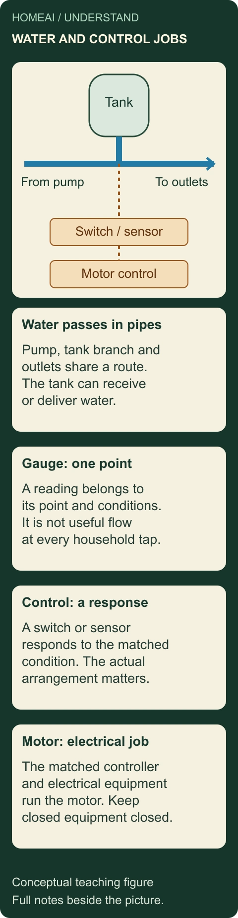
The water route carries water from the pump connection toward the tank branch and household outlets. A gauge observes pressure at its connected point. A switch or sensor responds to a pressure condition, while the matched controller and electrical equipment control motor operation. These are connected jobs, but a control signal is not another water pipe and a gauge reading is not a water-quality test.
Numbers identify the parts explained below.
- Water passes through pipes
The common supply connects the pump, tank branch and outlets. The tank can receive or deliver water through its branch as demand and pump delivery change.
- The gauge observes one point
A pressure reading belongs to the point, time and conditions of the observation. It is not automatically the pressure or useful flow at every outlet.
- The control responds
A matched pressure switch or sensor detects a relevant condition. Its response is part of the installed operating arrangement, not a universal setting.
- Electrical equipment runs the motor
The matched controller and electrical equipment carry out the motor-control job. Closed equipment identity and qualified assessment are the safe starting points.
What does this illustration leave out?
Conceptual roles only, not a wiring or piping layout. No actual sensing location, equipment rating, contact state, control setting, calibration or safe operating condition is established. Do not open a box, adjust a switch or reset a controller from this figure. This illustration explains an idea. It is not an installation guide.
Which actual component senses pressure, which controls the motor, and what does the recorded gauge observation describe?
Explore this with HomeAI ↗Opens an editable question. Nothing is sent until you choose to send it.Read the complete figure
Water flow and pump control have different jobs
The water route carries water from the pump connection toward the tank branch and household outlets. A gauge observes pressure at its connected point. A switch or sensor responds to a pressure condition, while the matched controller and electrical equipment control motor operation. These are connected jobs, but a control signal is not another water pipe and a gauge reading is not a water-quality test.
- Water passes through pipes
- The common supply connects the pump, tank branch and outlets. The tank can receive or deliver water through its branch as demand and pump delivery change.
- The gauge observes one point
- A pressure reading belongs to the point, time and conditions of the observation. It is not automatically the pressure or useful flow at every outlet.
- The control responds
- A matched pressure switch or sensor detects a relevant condition. Its response is part of the installed operating arrangement, not a universal setting.
- Electrical equipment runs the motor
- The matched controller and electrical equipment carry out the motor-control job. Closed equipment identity and qualified assessment are the safe starting points.
What remains unknown: Conceptual roles only, not a wiring or piping layout. No actual sensing location, equipment rating, contact state, control setting, calibration or safe operating condition is established. Do not open a box, adjust a switch or reset a controller from this figure.
A useful question: Which actual component senses pressure, which controls the motor, and what does the recorded gauge observation describe?
Why might a variable-speed system behave differently?
A conventional cycling system generally starts and stops the pump in response to its control conditions. A variable-speed arrangement can also change motor speed in response to changing demand. A pressure sensor supplies information to the drive, and the drive manages the motor. This adds another way of matching delivery to use rather than merely switching one fixed operating state on or off.
Pentair’s current Intellidrive page provides a named manufacturer example of this principle for submersible pumps. It distinguishes a pressure-switch arrangement from a drive responding to household demand. The manufacturer example explains a mechanism; it does not establish that this controller is installed, available, approved or suitable for a particular Canadian home.
A quieter or longer run can therefore have a different meaning depending on the control type. Applying the expected rhythm of one system to another may create a misleading complaint. Start by identifying the actual pump, motor, drive, sensor and tank. Ask the provider to explain the intended response to a small demand, a sustained demand and the end of use.
A variable-speed drive does not create groundwater or remove every restriction downstream. The well, pump, route, electrical supply and operating limits still matter. Marketing language about constant pressure should not become a promise that every tap will perform identically during any combination of uses. A site-specific assessment must establish the relevant conditions.
Compatibility is also a professional question. A drive, motor, pump and sensor cannot be selected by matching a cabinet colour or one horsepower value. Ask which exact combinations and instructions govern the proposed work and what findings support a change. No programming, electrical wiring or bypass procedure is provided here.
Keep software or configuration changes with the service history where the equipment uses them. Record who made the change, the intended purpose and the demonstrated result. A changed setting is a task; an improved response under a stated demand is an observation. Neither should erase an unresolved source, tank or distribution question.
Why does simultaneous water use matter?
Two fixtures using the same supply create a combined demand on their common route. A shower, washing-machine fill and irrigation use may overlap even when the household notices only one. The pump, available source, tank reserve and downstream pipes respond together. A changed shower stream during another use is therefore a useful description before it is a component diagnosis.
The route has physical effects as well. Water must travel through pipes, fittings and any treatment equipment, and reach outlets at their different elevations. Greater flow through a common route can change the pressure available farther along it. A professional can consider those conditions without assuming that adjusting the pump control is the appropriate first response.
The established water-pressure guide explains how to distinguish one outlet, one branch and a broader household complaint. Use that comparison here to keep a well-system investigation focused. If only one tap behaves differently, the fixture or its local connection may need attention even while the pump system serves other outlets normally. If several outlets change together, a shared part of the route becomes more relevant.
Treatment can add another operating context. A filter, softener or other device has its own intended flow and maintenance requirements. Its presence does not prove a restriction, and bypassing it is not an appropriate owner diagnostic experiment. Identify the exact equipment and let the relevant provider decide what assessment or comparisons are suitable.
A short ordinary-use log can be enough to improve the first appointment. Note the affected fixture, what changed, other known uses, approximate duration and whether usual delivery returned. Write unknown where another use was not observed. A truthful incomplete log is more useful than a detailed story built around an assumed quiet house.
Do not deliberately run multiple fixtures for a stress test, leave a pump running through a fault or attempt to reproduce a suspected leak. The provider can plan suitable measurements with appropriate safeguards. Ask them to state demand conditions and measuring points so the resulting report can be compared with the original household concern.
Two household uses share one supply route
A kitchen tap and a washing machine can draw from the same upstream supply at the same time. Their combined demand changes what the well, pump, tank and common route must deliver. A concern at one outlet may instead involve its own branch or fixture. Following the common route and then the branches keeps an observation from becoming an assumed pump-sizing diagnosis.
Numbers identify the parts explained below.
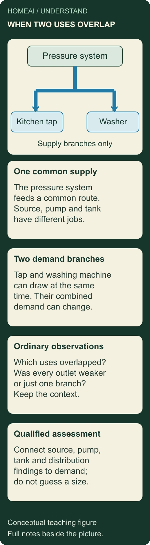
- One common supply
Water arrives from the pressure system through the shared upstream route. Pump delivery, usable tank reserve and source replenishment remain different questions.
- Two demand branches
The kitchen tap and washing machine are separate uses on this conceptual supply. Overlap can increase combined demand without showing how much either use requires.
- Compare ordinary observations
Record which ordinary uses overlapped when delivery changed. Keep whole-house changes separate from one outlet or one temperature-side observation.
- Match the assessment
A qualified provider connects source, equipment and distribution findings to the actual demand. A larger pump or tank is a proposal to justify, not a diagnosis supplied by the drawing.
What does this illustration leave out?
Conceptual supply branches only; drainage is deliberately omitted. No flow rate, pressure loss, pipe size, pump selection, appliance performance or actual household result is supplied. Do not run simultaneous demands as an improvised capacity test. This illustration explains an idea. It is not an installation guide.
Did the recorded change affect the common supply or a particular branch, and what ordinary uses were present?
Explore this with HomeAI ↗Opens an editable question. Nothing is sent until you choose to send it.Read the complete figure
Two household uses share one supply route
A kitchen tap and a washing machine can draw from the same upstream supply at the same time. Their combined demand changes what the well, pump, tank and common route must deliver. A concern at one outlet may instead involve its own branch or fixture. Following the common route and then the branches keeps an observation from becoming an assumed pump-sizing diagnosis.
- One common supply
- Water arrives from the pressure system through the shared upstream route. Pump delivery, usable tank reserve and source replenishment remain different questions.
- Two demand branches
- The kitchen tap and washing machine are separate uses on this conceptual supply. Overlap can increase combined demand without showing how much either use requires.
- Compare ordinary observations
- Record which ordinary uses overlapped when delivery changed. Keep whole-house changes separate from one outlet or one temperature-side observation.
- Match the assessment
- A qualified provider connects source, equipment and distribution findings to the actual demand. A larger pump or tank is a proposal to justify, not a diagnosis supplied by the drawing.
What remains unknown: Conceptual supply branches only; drainage is deliberately omitted. No flow rate, pressure loss, pipe size, pump selection, appliance performance or actual household result is supplied. Do not run simultaneous demands as an improvised capacity test.
A useful question: Did the recorded change affect the common supply or a particular branch, and what ordinary uses were present?
What can rapid cycling or a continuing run mean?
Rapid cycling means the pump appears to start and stop repeatedly over short intervals relative to its usual operation. One possible contribution is less usable tank reserve between control conditions. Other possibilities include ongoing water demand, a control or sensing issue, or a delivery arrangement that no longer behaves as expected. The observation names a pattern, not the failed part.
A continuing run asks a different question. The system may be meeting a continuing demand, may be unable to reach the intended stopping condition, or may have another source, delivery or control problem. A low-yield condition is one possibility, not a conclusion from motor sound. Stop using the pattern as a reason to keep the machine operating while trying one reset after another.
Starts when the household seems quiet also need context. Toilets, treatment regeneration, irrigation and appliances can use water automatically. A leak or unintended return path can be relevant too. Have the provider determine which actual demands and connections explain the event. Do not assume that a quiet room means every connected water use has stopped.
A weak stream, air at a fixture, sand or a change in appearance should be described separately. These observations can have different source, pump, route and water-quality implications. Tell the provider what occurred and obtain appropriate health advice if safety of the water is uncertain. An equipment repair must not be treated as a laboratory clearance.
The three-symptom figure compares repeated starts, continuing operation and a local delivery complaint. Its branches show useful questions: how much reserve is available, what demand is present, whether the matched control responds, and which part of the route was examined. None of its branches tells the reader to replace a named part or adjust a setting.
An intermittent event may not recur during one visit. Preserve that result honestly, including what the provider could assess and what further monitoring they recommend. A quiet ten-minute visit does not erase a dated event, while a reported sound does not override a measured finding. Keeping both accounts allows a better follow-up question.
Urgent conditions change the task. Escaping water, wet electrical equipment, abnormal overheating or another apparent immediate hazard requires staying clear and arranging appropriate emergency or qualified assistance. Do not open the pump house, cross wet flooring or operate unfamiliar equipment to complete the log. Evidence gathering should support safe service, never delay it.
Changed cycling needs a specific question
Frequent starts, a continuing run and weak delivery at one outlet are different observations. A changed usable tank reserve may be relevant to cycling; source, demand or delivery conditions may be relevant to a continuing run; a local branch can matter to a single outlet. These are investigation paths with alternatives, rather than pictures of confirmed failed parts.
Numbers identify the parts explained below.
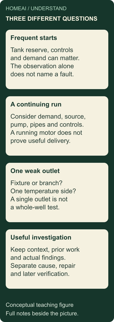
- Frequent starts
Ask how usable tank reserve, controls, demand and any other relevant delivery findings fit the changed pattern. More frequent starts do not alone confirm a waterlogged tank.
- A continuing run
Ask about demand, source availability, pump delivery, piping and the actual control arrangement. A running motor does not prove adequate water movement or select one failed component.
- One weak outlet
Ask whether the concern belongs to that fixture, its branch, one temperature side or a wider supply change. A single outlet is not a whole-well capacity assessment.
- A useful investigation record
Preserve ordinary-use context, previous work and qualified findings. The provider should state the observed cause, scope, completed work and relevant follow-up separately.
What does this illustration leave out?
No failed tank, exhausted well, leaking pipe or defective control is diagnosed. A sound, brief pressure observation or one fixture’s stream cannot isolate the cause. This figure supplies no reset, adjustment or owner test procedure. This illustration explains an idea. It is not an installation guide.
Which observation is being investigated, what alternatives remain, and which findings support the proposed work?
Explore this with HomeAI ↗Opens an editable question. Nothing is sent until you choose to send it.A pattern should become an assessment question
- Repeated short startsAsk about demand, usable tank reserve and matched sensing/control response.
- Continuing runAsk about continuing demand, delivery, source and ability to reach the intended control condition.
- One weak outletAsk about the fixture/local route before treating it as a whole-well complaint.
Alternative explanations, not a fault diagnosis or owner test.
Further reading: Government of Alberta · Pressure Tanks, Agdex716(C31); Government of Alberta · Deep Well Jet Pumps, Agdex716(C11); Government of Ontario · Managing your water well in times of water shortage.
Read the complete figure
Changed cycling needs a specific question
Frequent starts, a continuing run and weak delivery at one outlet are different observations. A changed usable tank reserve may be relevant to cycling; source, demand or delivery conditions may be relevant to a continuing run; a local branch can matter to a single outlet. These are investigation paths with alternatives, rather than pictures of confirmed failed parts.
- Frequent starts
- Ask how usable tank reserve, controls, demand and any other relevant delivery findings fit the changed pattern. More frequent starts do not alone confirm a waterlogged tank.
- A continuing run
- Ask about demand, source availability, pump delivery, piping and the actual control arrangement. A running motor does not prove adequate water movement or select one failed component.
- One weak outlet
- Ask whether the concern belongs to that fixture, its branch, one temperature side or a wider supply change. A single outlet is not a whole-well capacity assessment.
- A useful investigation record
- Preserve ordinary-use context, previous work and qualified findings. The provider should state the observed cause, scope, completed work and relevant follow-up separately.
What remains unknown: No failed tank, exhausted well, leaking pipe or defective control is diagnosed. A sound, brief pressure observation or one fixture’s stream cannot isolate the cause. This figure supplies no reset, adjustment or owner test procedure.
A useful question: Which observation is being investigated, what alternatives remain, and which findings support the proposed work?
Would a larger tank or a storage cistern solve the problem?
A pressure tank stores a useful amount of water while its compressed-air condition supports delivery. A bulk storage cistern primarily holds a larger volume of water and may feed a separate pump and pressure arrangement. They can belong to the same overall supply, but they solve different physical tasks. Similar blue water in a cutaway does not make their storage roles interchangeable.
More usable pressure-tank reserve can change the interval between pump starts for a given demand. It does not by itself increase groundwater replenishment or remove a pipe restriction. The appropriate selection depends on the actual pump and control system. Ask the designer or service professional to explain the reserve, intended operation and reason for the proposed size.
A separate cistern can allow water to be collected at one rate and used at another within a properly planned arrangement. It adds equipment, storage hygiene, source, controls and maintenance questions. A larger container is not an automatic answer to an inadequate source, and a stored volume is not a promise of safe drinking water.
Ontario’s shortage guidance lists storage among possible responses while also asking for source and equipment assessment. Those are options for a qualified site-specific discussion. This article adopts no container size, pumping schedule, low-yield threshold, drinking-water treatment plan or design for adding another tank.
Ask what the proposal changes and what remains. Does it address tank reserve, a demonstrated equipment fault, a mismatch with intended demand or a professionally established source limitation? Which existing pump, controller, treatment and pipes will remain? Keeping that explanation beside the quote makes alternatives comparable without turning an owner into the designer.
Include operating responsibility in the decision. A storage arrangement may require additional monitoring, cleaning, service, power and seasonal protection under its own instructions. Ask who supplies those requirements and what happens during a fault. A lower initial price or a larger advertised volume alone cannot establish the more appropriate long-term arrangement.
Bulk water storage and a pressure tank solve different parts of delivery
The pressure tank on the left combines water with a compressed-air cushion for delivery between pump runs. The larger cistern on the right represents bulk water held before a separate booster pump and pressure system. A cistern can change how stored supply and later household demand are managed; it does not create more groundwater or establish the quality of stored water.
Numbers identify the parts explained below.
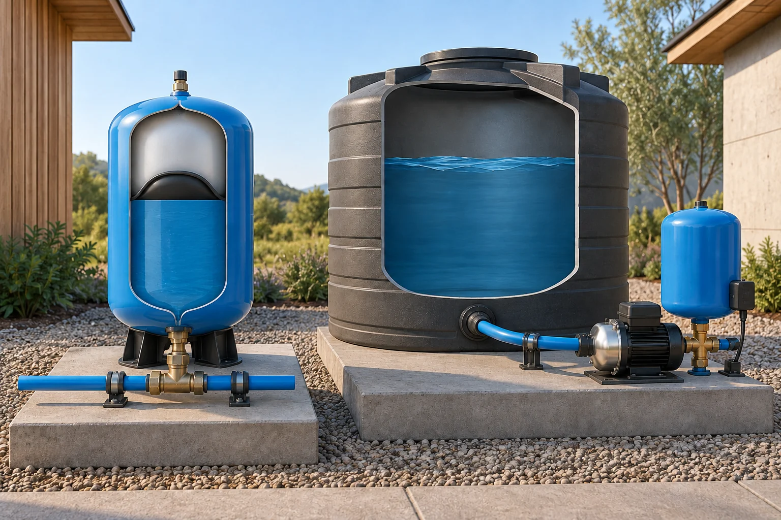
- Pressure storage
The smaller left vessel illustrates a water reserve delivered by compressed air. Shell size alone does not give usable water between the actual control points.
- Bulk water in a cistern
The closed larger vessel illustrates a separate stored-water role. Ask how source availability, storage and water quality would be managed for a real proposal.
- Booster and pressure system
The downstream pump moves stored water toward the smaller pressure tank and supply connection. Selection and control require an identified design and qualified scope.
What does this illustration leave out?
These are separate conceptual arrangements, not one installed property or a recommended outdoor layout. Cistern filling, complete distribution, freeze protection, sanitation, safe support, capacities and control details are omitted. The pressure-tank cutaway is illustrative. This illustration explains an idea. It is not an installation guide.
Does the proposed work address usable pressure reserve, source availability, bulk storage or another issue, and what findings justify it?
Explore this with HomeAI ↗Opens an editable question. Nothing is sent until you choose to send it.What changes during a power interruption or freezing weather?
The pump needs its intended power supply to add energy to the water. When that supply is unavailable, a conventional pressure tank may deliver some remaining reserve under the existing conditions. That reserve is limited and is not a reliable emergency water allocation. Continued delivery at one moment does not establish that the pump is running or that the household can continue ordinary use indefinitely.
Controls, drives and protective functions have their own power and restart requirements. Ask the provider to explain the actual system’s response and the appropriate household plan. Do not bypass a control, connect a generator through improvised wiring or assume that an available socket can supply the pumping equipment. Backup-power work needs its own qualified design and instructions.
Freezing exposure also concerns the complete route: wellhead arrangements, buried and exposed pipes, the pump house or mechanical space, and any temporary storage or lines. A warm room around the tank does not establish the condition of every remote section. Seasonal protection must fit the actual installation and local conditions rather than a single national depth or temperature rule.
The owner’s useful contribution is to report changes from safe ordinary access. Note when supply changed, whether an outage or unusual cold occurred, any safely visible warning and the relevant history. Do not apply a flame, heat an unidentified pipe, remove insulation or operate equipment to test a suspected frozen section. Qualified assessment should establish the route and appropriate response.
Flooding near a well or equipment introduces separate source-protection and electrical questions. Do not enter a well pit or wet equipment area. If the water supply may be contaminated, obtain current local health instructions and a suitable alternative rather than rely on the fact that the pump still runs. Quality and delivery remain distinct during an emergency as well as during routine service.
At a seasonal reopening, discuss time out of use, possible damage, service history and the checks needed before reliance. This guide gives no universal restart, flushing, disinfection or valve sequence. A written system-specific plan helps the household recognize what it can observe and which task belongs to the well contractor, plumber, electrician or health adviser.
Which measurements and records answer which question?
A well record describes the source and construction information recorded for that work. A professionally scoped pumping assessment can investigate water levels, rate, duration and recovery under stated conditions. These can help address source quantity. They do not automatically establish the operation of every household fixture or the condition of a pressure tank’s separator.
A delivery assessment records pressure and flow at identified locations under specified demands. It may help separate an entry-system issue from a downstream route or fixture issue. Ask which gauges or methods were used, what the operating conditions were and which parts of the installation were outside access. A statement that pressure was good leaves important questions open without that context.
Tank and control assessment concerns the matched vessel, air condition, usable reserve and operating response. The provider decides what safe isolation, access and measuring procedure is required. Ask the report to distinguish a measured condition from a visual impression and a recommended action. A shell photograph, a switch replacement and a verified cycle are different pieces of information.
Electrical investigation concerns the relevant power supply, motor and controls within the qualified provider’s scope. A device label or lit indicator does not demonstrate appropriate electrical condition. The well or pump specialist may coordinate with an electrician where required; a general home-inspection report should not be assumed to include intrusive electrical or down-well testing.
Water-quality reports describe specified samples and parameters. Keep their sample locations, dates and treatment conditions intact. They belong beside the equipment record because the supply is connected, but their scope remains separate. A new pressure tank does not prove safe water, and a reassuring bacteria result does not prove adequate pump delivery.
For any proposed test, agree on the question, method, permissions, conditions and written deliverable before work. Ask what the test can establish and what uncertainty remains, including seasonal differences. The four-record figure helps the household request those deliverables without asking every provider for the same vague all-system certification.
After work, keep the original observation, finding, completed task and follow-up together. If a later report changes the understanding, add it with its date rather than rewrite the first observation as though the cause was known then. This makes a continuing service question easier to understand and leaves a more honest record for a future owner.
Four records answer four different water questions
A well or recovery record concerns the source under its recorded conditions. Pump-delivery measurements concern moving water through a particular installation. Tank and control findings concern cycling and usable reserve. A water-quality result concerns the sampled water, location, constituents and date. Keep these records together while preserving their separate jobs.
Numbers identify the parts explained below.
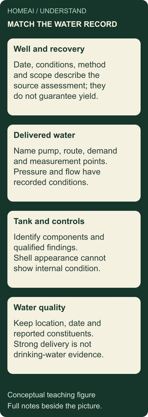
- Well and recovery
Retain the date, source conditions, method and scope of the actual source assessment. A drilling-era observation is not automatically today’s level or future yield.
- Pump and delivered water
Identify the pump, route, demand and measurement points. Pressure and flow findings belong to their actual operating conditions and test scope.
- Tank and controls
Record the exact components, observed cycling, qualified findings and completed work. The shell’s appearance does not establish internal air condition or matched control performance.
- Water quality
Keep sample location, date, treatment conditions, reported constituents and advice. Strong delivery or recent pump work does not establish drinking-water suitability.
What does this illustration leave out?
No actual pumping assessment, measurement, water result, installed condition or future supply guarantee is supplied. An old source record or new equipment invoice cannot substitute for every other scope. This illustration explains an idea. It is not an installation guide.
Which record answers the current concern, and which other source, delivery, control or water-quality question remains open?
Explore this with HomeAI ↗Opens an editable question. Nothing is sent until you choose to send it.Keep four kinds of evidence separate
- Source and recoveryIdentified well, levels, pumping rate/duration and interpreted recovery.
- Pump and distributionActual equipment and delivery at named points under stated demand.
- Tank and controlsMatched vessel, usable reserve and assessed operating response.
- Water qualityNamed sample point, date, parameters and health/treatment interpretation.
Each deliverable retains its own methods, qualifications and unassessed areas.
Further reading: Government of Ontario · Managing your water well in times of water shortage; Pentair · WellMate frequently asked questions.
Read the complete figure
Four records answer four different water questions
A well or recovery record concerns the source under its recorded conditions. Pump-delivery measurements concern moving water through a particular installation. Tank and control findings concern cycling and usable reserve. A water-quality result concerns the sampled water, location, constituents and date. Keep these records together while preserving their separate jobs.
- Well and recovery
- Retain the date, source conditions, method and scope of the actual source assessment. A drilling-era observation is not automatically today’s level or future yield.
- Pump and delivered water
- Identify the pump, route, demand and measurement points. Pressure and flow findings belong to their actual operating conditions and test scope.
- Tank and controls
- Record the exact components, observed cycling, qualified findings and completed work. The shell’s appearance does not establish internal air condition or matched control performance.
- Water quality
- Keep sample location, date, treatment conditions, reported constituents and advice. Strong delivery or recent pump work does not establish drinking-water suitability.
What remains unknown: No actual pumping assessment, measurement, water result, installed condition or future supply guarantee is supplied. An old source record or new equipment invoice cannot substitute for every other scope.
A useful question: Which record answers the current concern, and which other source, delivery, control or water-quality question remains open?
What should qualified maintenance and handover include?
The maintenance plan begins with equipment identity and the applicable instructions. A well pump, tank, pressure switch, drive and treatment device have different requirements. Ask the provider which routine tasks apply to the actual arrangement and which require qualified access. A historical leaflet’s general statement about low maintenance is not a reason to ignore changed behaviour or a current manual.
A useful handover explains ordinary operation in familiar terms: where water comes from, what the tank does, which controls should be observed and whom to contact about a fault. Ask the provider to identify safely accessible labels and any areas the homeowner should not enter. This knowledge is useful before an outage or delivery problem, while the installation is dry and operating normally.
Service tasks that open a pressure vessel, expose electrical parts, disturb the well or alter controls belong to appropriately qualified work. Do not turn a checklist into permission to recharge a tank, change a pressure setting, reset a protective function or run a pump without an established supply. The professional should explain any temporary restrictions while the work or investigation remains incomplete.
Ask the well contractor what qualifications and authorizations apply locally, and ask each specialist to state their role. Plumbing distribution, electrical supply, source construction and water-quality interpretation may need different expertise. The presence of one contractor’s logo or a general inspection label does not establish competence or coverage for every part.
For a replacement, retain the exact installed model, the reason for the change, components kept, relevant instructions and the checks actually performed. A receipt for a new vessel without its matched operating information leaves the next service person reconstructing the system. A good completion record also names unresolved concerns and who owns the next task.
Review the plan when household uses change, equipment is replaced or recurring symptoms appear. Added irrigation, another occupied suite or a seasonal change may alter the demand question. That is a reason to discuss the design basis, not to assume an automatic failure. Keep the actual change and the provider’s response with the same dated system record.
What changes across Canadian regions and source editions?
The physical jobs of pumping, compressed-air delivery and control are useful across Canada. The actual source, construction, climate, qualifications and requirements are local. Ontario’s owner information describes its provincial well arrangements; it should not be silently used as another province’s legal rule or as a universal property-transaction condition.
Several Alberta pump and tank publications retained here are clearly historical: pressure tanks revised April2005, submersible pumps January2007 and deep-well jet pumps March2008. They explain mechanisms and older arrangements. Their installation instructions, design numbers, contacts and broad maintenance statements are not adopted as current universal owner instructions.
Manufacturer examples also have defined limits. The WellMate FAQ is a US page about identified product families, while the current Pentek page describes its own drive. A reachable page does not establish the manual for an older installed unit or Canadian-market approval for a proposed combination. Confirm the exact equipment and its applicable current documentation with the provider.
Keep dimensions, pressures, electrical settings and sizing calculations in the qualified design or service record. This guide deliberately supplies no generic tank air setting, pump-start number, maximum cycling rate, well depth or nationwide burial depth. Those details would be misleading without the actual equipment, purpose and local conditions.
Source dates help explain what the guide can support. They do not make the reader’s home a copy of the published example. Use this explanation to follow the mechanism and request a specific assessment, while preserving immediate safety, current public-health advice and the local authority’s role for actual work.
How would a fictional household investigate changed cycling?
In this invented example, Morgan notices several short pump sounds during ordinary kitchen use. The household has a drilling record, a tank-replacement invoice from a previous owner and an unidentified closed control box. No pressure readings or source-level measurements are available. The starting record describes repeated sounds, not a confirmed failed tank or exhausted well.
Morgan records the time, fixture and known simultaneous use from a dry ordinary position. One entry includes a washing-machine fill; another says other use unknown. The tank invoice identifies a past task but not the present usable reserve or control configuration. Morgan does not press an air valve, open the control box, force a shutoff or run a prolonged test.
The service request asks the well professional to identify the pump/tank/control arrangement and investigate the changed operating pattern. It also asks which distribution and electrical questions the visit can cover and whether another provider is needed. Existing well, treatment and service records are supplied with their original dates rather than summarized as proof that everything was checked.
In the invented professional report, the identified tank has reduced usable water reserve between the assessed control points. The report recommends tank-related work, while expressly leaving well replenishment and water quality outside that visit. This narrows Morgan’s decision: obtain the finding-linked tank scope rather than accepting an unsupported proposal to replace the well pump. The example supplies no pressure setting, test procedure, real diagnosis or promised improvement.
After the qualified work, Morgan obtains the exact model information, recorded operating checks and the provider’s instructions for future faults. Later ordinary-use entries describe whether the original pattern recurs under the known household demands. A quieter evening alone is not presented as all-season proof; the follow-up retains its actual observation period.
Consider the alternative branch: the visit does not reproduce the event and recommends a defined further investigation. Morgan preserves that conclusion instead of converting it into no problem found anywhere. The dated log helps the next provider distinguish the observation, what was measured and which question remains unanswered.
The drinking-water record stays separate throughout. A delivery repair does not change the meaning of an earlier sample or replace local health advice about a new quality concern. The useful outcome is a system the household can explain, a finding-linked service history and a clear owner for each remaining task, rather than a reassuring label applied to all water questions.
Keep learning about the connected parts
- Know what your private well is supplying
- Buying a home with a well: quality, quantity and the record
- Low water pressure: build a useful observation log
- Home water filters and UV treatment: understand what each part does
- Water leaks explained: find the right question before the repair
- Prepare exposed plumbing for a cold spell
- Build a home-care record that the next person can understand
- Rainwater collection: follow the roof, the store and the overflow
Canadian context and authorities · Visual atlas · Learning labs
Practice the distinction.
Morgan hears a changed pump rhythm
Fictional household case: repeated sounds occur during ordinary use, with old well/tank records but no current readings.
Reported observations
- Ordinary entries include a washing-machine fill and another period with other demand unknown.
- The invented report identifies reduced usable reserve in the named tank; well replenishment and water quality were not assessed.
- No owner opens equipment, adjusts pressure or stages a delivery test.
Compare the explanations
Expand each possibility to see the evidence needed to distinguish it. Similar symptoms can have different mechanisms.
Tank or control behaviour needs assessment
Usable reserve, sensing and matched operating response can contribute to repeated starts.
Qualified tank/control findings with methods, conditions and actual equipment identity.
Demand, delivery or source contributes
Automatic uses, distribution and well conditions can ask different questions.
A scoped investigation distinguishing observed demand, measured delivery and source quantity.
A useful next question
Match the tank-related proposal to the invented finding, retain the excluded well and quality questions, and request completed-work evidence if the proposal proceeds.
No actual pressure, diagnosis, repair cost, water-quality clearance or all-season performance is supplied.
Know what the words mean.
- Tank draw-off
- The useful water delivered between specified control conditions; different from the vessel’s total volume.
- Air cushion
- Compressed air that can expand as stored water is delivered from a pressure tank.
- Pressure switch
- A control that responds to pressure conditions as part of starting and stopping a pump.
- Variable-speed drive
- Matched motor-control equipment that can change pump motor speed in response to the system’s demand signal.
- Impeller
- A rotating water-moving part inside a centrifugal pump.
- Well drawdown
- A change in well water level during pumping, interpreted with the test’s rate, duration and recovery information.
Questions to bring
to the conversation.
- Which well, pump, tank and control arrangement actually serve this home?
- What changed during ordinary use, and which other demands were present?
- Which measurements and safe access does the qualified investigation require?
- Does the report distinguish source quantity, delivered pressure/flow and tank/control performance?
- Which completed work and comparable follow-up answer the original concern?
Separate a showing observation, an existing record and a new professional assessment. Unknown means a question remains; it does not automatically mean a defect.
Use the evidence planner ↗Go to the source.
Original HomeAI explanation informed by these public references. Sources support the underlying guidance; they have not reviewed or endorsed HomeAI. Diagrams are conceptual, and calculator outputs depend on your inputs.
Primary source bodies were read October13,2026. Alberta tank/pump leaflets are historical2005/2007/2008mechanism references; no installation, sizing, air-setting, cycling-limit or maintenance instruction is adopted. Ontario shortage guidance is updatedJune7,2022and remains Ontario-specific; its DIY well-level procedures are not reproduced. Current reachable Pentair pages are named manufacturer examples without a presumed publication date or Canadian approval. The full captured Ontario equipment/maintenance chapters, reversed1993table and incomplete rasterEnglish manuals are not claimed as fully read or used for new claims. No well access, tank recharging, switch adjustment, priming, wiring, pump retrieval or deliberate capacity test is supplied. Qualified current equipment/local advice governs actual work.
Publication & source review
First published .
Sources reviewed .
- Electrical Safety Authority · Flood Safety
Where this reference applies
Jurisdiction: Ontario electrical authority; local utility and qualified-response arrangements differ elsewhere
Edition: Undated current substantive body; copyright is not treated as a revision date.
Source reviewed: 2026-10-13 · America/Edmonton
Reading scope: Complete substantive web/ordinary HTTPS 200 body read in owner/esaFloodCurrent.*. The earlier guessed path redirected to an unrelated EV page, retained as a hold and excluded.
Electricity can travel through water/wet flooring; remain out of affected areas near electrical equipment and arrange utility/qualified help. No owner electrical-disconnection, repair or restoration procedure adopted.
- Government of Alberta · Pressure Tanks, Agdex716(C31)
Where this reference applies
Jurisdiction: Alberta; historical farm-water education
Edition: Revised April2005; no later revision inferred.
Source reviewed: 2026-10-13 · America/Edmonton
Reading scope: Complete two-page primary PDF text read; original retained in roadmap-wave2-20261013/owner/abTank2005.pdf.
Compressed-air delivery, usable water between cycles, air/water contact versus diaphragm separation and why reduced air cushion can change cycling. No historical sizing, cycle limit, air setting, installation or service procedure adopted.
- Government of Alberta · Submersible Pumps, Agdex716(C14)
Where this reference applies
Jurisdiction: Alberta; historical farm-water education
Edition: Revised January2007.
Source reviewed: 2026-10-13 · America/Edmonton
Reading scope: Complete three-page primary PDF text read and retained in owner/abSubmersible.pdf.
Submerged motor/impeller/diffuser mechanism, relationship of lift and discharge pressure to delivery, source matching and sand/dry-operation concerns. No installation, wiring, horsepower, depth, pressure, start-up or maintenance instruction adopted.
- Government of Alberta · Deep Well Jet Pumps, Agdex716(C11)
Where this reference applies
Jurisdiction: Alberta; historical deep-well jet-pump example
Edition: Revised March2008.
Source reviewed: 2026-10-13 · America/Edmonton
Reading scope: Complete three-page primary PDF text read and retained in owner/abJet.pdf.
Above-ground impeller, down-well injector, drive and return paths, priming dependence and possible obstruction/air contributions. No priming, valve operation, pulling, adjustment, depth-selection or repair procedure adopted.
- Government of Ontario · Managing your water well in times of water shortage
Where this reference applies
Jurisdiction: Ontario; provincial owner information, not nationwide legal or installation advice
Edition: Updated June7,2022; published July29,2016, PIBS3784e.
Source reviewed: 2026-10-13 · America/Edmonton
Reading scope: Complete substantive ordinaryHTTPS200 body read in two portions after the web-tool access hold; owner/ontShortage.html and .txt retained.
Source and equipment alternatives, well/pump matching, demand and historical records, specialist investigation and confined-space/electrical hazards. HomeAI does not adopt the page’s DIY water-level-measurement instructions or historical contact/fee details.
- Pentair · WellMate frequently asked questions
Where this reference applies
Jurisdiction: US manufacturer page; identified WellMate examples only
Edition: Undated current reachable body; no revision date established.
Source reviewed: 2026-10-13 · America/Edmonton
Reading scope: Complete substantive HTML body read and retained in owner/pentairFAQ.html and .txt.
Tank air-cell and conventional air-volume differences, component identity and model-specific service boundaries. No numerical air/temperature/pressure setting, treatment claim, retrofit or homeowner procedure adopted.
- Pentair · Pentek Intellidrive PID Variable Frequency Drive
Where this reference applies
Jurisdiction: Manufacturer product example; no Canadian-market approval or universal compatibility inferred
Edition: Current reachable product body, no substantive revision date established.
Source reviewed: 2026-10-13 · America/Edmonton
Reading scope: Complete substantive product HTML read; ordinaryHTTPS200 capture owner/currentVFD.html and .txt. The partially rasterized2009brochure is not used as a full-reading source.
Motor-speed response to household demand and distinction from an on/off pressure-switch arrangement. No marketing guarantee, savings, noise, life-extension, horsepower or programming claim adopted.
Have a question about your home?
Start with the symptom, timing and what you have observed.
Ask HomeAI